Magnus' Calrec PQ1549 DIY-page
Welcome to Magnus' beginners guide to the Calrec PQ1549
This page is written and photographed by Magnus Johansen.
10. Jan. 2003
Magnus Johansens go at the Do-It-Yourself Calrec PQ1549 EQ
This is an attemt to make a sort of a beginners guide to the CALREC EQ DIY project. This is from what I think a great first time project. No really hard to get components, no trimming and if everything goes the way it should you just have to put the mains plug in the wall and start use your new equipment. Many of you might have another way to get through a project like this but this is sort of the way I do it and I hope this is going to give at least new interested people a hint or two. But of course everything can happen when "Murphy" is around so??? We´ll try to avoid him.
Along the road to compete Eq we have to pass some tricky moments. They might seem a little hard first but it isn´t worse than it could be done. I mean if I could get through so why shouldn't you. Ok here are the different stages:
1. Buying the components.
2. Making the PCBs.
3. Populate the PCBs.
4. Testing.
5. Eventually there is some fault finding.
6. Put it in a box.
Then hopefully is the time to enjoy your studio upgrade.
Maybe here is a good place to introduce myself. A Swedish guy 32 years old. Studied electronics 1986-88 but hasn´t done anything with it before I found Group DIY recently.
Got into guitar playing 89 and that lead me into recording, studied for sound engineer 95. So there I was building my own homestudio, broke but happy and that's how I got into DIY, reading a compressor test that were compared with the UREI 1176 so I searched the net and found Gyrafs DIY page and here I am a couple of projects later.
Buying the components:
Try to find a dealer/ dealers for the complete project before you start it, cause you might end up with an incomplete unit who will end up in the closet and never be used…( Have a lot of these at home )…The things I had a little problem finding was the switches cause I don't have any company so I couldn´t buy from Farnell and they got at least most of the parts for the project. But I´m still searching, otherwise I´ll have to use some other type of switches, my PCBs is just hard wired for the moment. It works but is a little limited way to use it.
Then we have the neg log pots, they can be a little tricky to find unless you don't find them as spares from any other Eq or board ( Expensive I guess ) But Jakob found them as spares at monacor very cheap. I got mine from rebuilding usual log pots the way Jakob describes on his page.
Here are some pics from my rebuilding. It isn´t to hard to do it, a little bit tricky cause its so small but all it is about is to change places of the carbontracks on opposite sides of the slider. See the photos for details, they speak for themselves.
Pictures of Rebuilding a Stereo Log pot to Stereo Neg. Log.
Exept for this there are no real hard to get components I guess, Contact your local dealer for info.
Making the PCBs:
I have just got the equipment for this so I´m just a beginner but the whole thing isn´t that hard so don't be afraid to try for yourself. I am using the easiest and cheapeast way possible I think.
¤ 2 printed overheadfilms for laserwriter with the PCB layout in scale 1:1. Put both of them in top of each other to make it more black so the UV lamp won´t shine through it.
¤ 1piece 300w Osram (or other brand ) UV lamp that I put 44 cm over the pcb.
¤ 2 small 3mm glass windows ( maybe 20x30cm ) to place the PCB and overheadfilms between.
¤ 2 plastic boxes where you can develop and etch. ( I used 2 litres icecreamboxes )
¤ About 6 clothes pegs
¤ And of course the etch and develop liquid that you bought from your dealer.
¤ 2 Large Sauce pan with hot water that is wide enough to have room for one of the plastic box.
I just take the PCB, overheadfilms and windows in a quite dark room, put one window in the bottom ant then place the pcb ( rip off the safety film ) over it. Put the OH film over the PCB where you want it and place the 2nd window on top. Lock the 2 windows together using the clothes pegs and put it all under the lamp.
My lamp is just hanging in the cable from the roof. (It works, why fix it..)
I use pcb card with FR4 photoresist and we have figured out that 30 minutes is about right time to let it shine on the cards. If you have any other photoresist you may have to change the time to light on the PCBto get it right.
Then I take it out of the glass and put it in the develop liquid ( about 30 seconds ) Just as much liquid that it covers the PCB and maybe 5 mm more and the same for the etching. You see a black "smoke" coming from the PCB into the solution, and the tracks starting to be visible. Just when the black smoke stoppes to come its finished.
Then I just put it under the water tap (yes I do this in my kitchen) and in to the etch liquid. The liquid I use works best in about 50 degrees C, so I just put the box floating in a waterfilled sauce pan (which I already have heated) and after about 15-20 minutes I got my PCB ready. Its not harder than that, maybe a little trial end error to get the time under the lamp right but otherwise its quite easy.
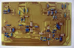
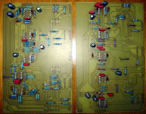
Populating the PCBs:
Things to be real careful at now is that every component fits in the right spot and is turned to the right direction. So a very helpful hint is, don't rush this cause a little mistake here can take quite a while to find later in the startup.
Start with the copper wires and resistors and work your way up to the lager components, but I don't put the Ics in place. For every one you put in place you remove it out of the partlist and on the PCB layout and when you are finished here you should have no components left and no place unpopulated.
Then it´s just to get the connection wires between the PCB cards and and from the powersupply in place.
Testing:
I usually start this sequence by looking at the soldering on the PCB cards, look for short circuits between tracks and that every soldering looks ok.
Then I measure between -18v and +18v and ground if there is any shortcircuits.
If I´m clear so far, I go further by connecting the power but I don't have any IC connected. So now its time to measure if I have the right power to the right pins on the IC's, cause if there is something wrong here, it may burn the IC and we can get very tricky faults to find.
If everything goes well so far, its just to put the IC in place and try again; and if there is no current rush I´ll plug in the CD player and connect the output to my amp. That is the way I do this, but I guess there is a 100 ways to do it. If there isn´t any problems here, its just to move on and put the eq in a box, otherwise there is a little faultfinding to do.
Faultfinding:
Well here is the sad part, sometimes it simply won't work. But the good news is that it's quite fun to do this and I always seem to learn a bit more when I do it.
The equipment we need to do this is at least a multimeter and, if it is possible, even an oscilloscope and a signal generator. But if you don't can borrow a scope, we'll have to try to do this anyway.
It is a good start to make a list of what is wrong with the unit, try to be as precise as possible:
Ex: "The sound is distorted"
- is it like that whit the pots in any possition
- does it make a difference if you lower the input signal
- and so on.
This helps us to try and locate the problem
From what I have experienced, is that the most usual kind of faults is soldering blobs, so start to look at the copper side of the PCB, at least when we're doing "tested" projects like this. This can be a little hard to find 'cause a short circuits isnt always visible with eyes only.
If there is one of the filter that isnt working it's a good start to search around this part of the pcb.
Then we have the next kind of problems - is every component in the right place, and is the Ic's in the right direction. In this project it is quite simple to check this, cause the PCB layout is correct but otherwise we have to check and doublecheck with the schematic.
Does every IC have the right voltage power? Check this with the multimeter (even if we did this at the start up procedure).
I hope that these tips have helped you ( or that you haven´t had to pass this part at all ) but remember don't give up. Even when it feels hopeless every fault is solveble. You can always contact the Jakob or Me or anyone else at Group DIY to ask questions (see adresses below).
Putting it in a box:
Almost complete. Here we have 2 options I think.
To build a box or buy it.
If you are going to build one, I guess you already have knowledge in mechanics, so we leave this part here. Otherwise you have to find a dealer that can sell a box to you, and then you just have to drill the holes in the front panel for pots and switches.
The Pcbs ar hanging in the pots so this is quite easy to mount. The power supply unit is mounted somewhere in the back near the power inlet. Drill the holes for ins and outs, and connect the cables to the PCBs. The front panel would be nice with some markings on it, and there are many ways to do this.
Links at this part of works is avaliable at Group DIY.
Now is the time to enjoy your new studio upgrade. Feel free to mail Jakob or me with questions or feedback of the project.
Magnus: 243104@worldonline.se
Jakob: Jakob@gyraf.dk
Thats all people / Magnus
Also check out Kev Ross' DIY-Page on Recording.org, with a lot of good links for this type of projects:
KEV'S DIY GROUP PAGE ON RECORDING.ORG
The Recording.org forum would be a good place to ask questions about this project:
The "Tech Talk" forum
HOME
Shown:
01-2003
Magnus Johansen
05-01-2003