The SSL Clone
The SSL Clone
The SSL Mixbus Compressor Clone
10-05-2006
This is a design I did way back in my early years, so you'll have to bear with the ugly pcb layouts. And sorry, this design is absolutely free from tubes and transformers. But it has a nice moving coil meter at least.
My reason for doing this clone is that the SSL is one of the worlds widely recognized stereo mix compressors - it has a well known sound, and is lusted after by many recording engenieers. But the SSL4000 desk is prized as to be out of reach for most small studio owners. This design is - as you'll see - quite simple, easy and economically reachable, so I thought it would make a fine DIY-project for people that know their soldering iron and wants to start building pro quality DIY audio equipment. The beauty of this design is that - contrary to a lot of other esoteric projects - the components are (relatively) easy available anywhere, and no special knowledge, tools or adjustments are needed.
The compressor is cloned from our good old SSL4044E desk, dating back from '85. The SSL mixbus compressor is an integral part of the mixer's main quad fader and autofade system - cards 82E26 and 82E27, and as you can see if you compare these to my schematic, a series of changes have been made for rehousing the circuit. The main changes concerns the electronically balanced input and output and the removal of unneded components regarding the autofade and main fader circuits. Another change is that the sidechain is common to both VCA's, making better tracking abilities - your mix wont' "tilt" so easy when you're compressing heavily. We did things like that to the SSL in the old days. This might seem like a big change, but actually the sonics are preserved very close to the original, and tracking errors are cancelled.
THE CIRCUIT:
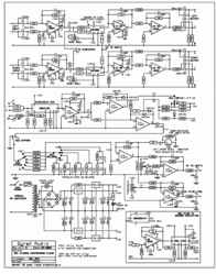
Schematic for The SSL Clone
The anatomy of this compressor is surprisingly simple:
Input signals are de-balanced by a couple of NE5534's, who in turn are driving the VCA in current mode via 27K resistors - the THAT VCA's are current in - current out devices (note that on the old component overlay, these resistors are marked 15K look here). From the VCA's the signal is taken to a current-to-voltage converter combined with a simple, yet proven, balanced output drive stage, consisting of two NE5532's. This concludes the story of the audio path. Not much electronics to mess up your precious audio signal here.
The signals from the input opamps are also summed via 47k's and sent to the input of the sidechain VCA. The purpose of this VCA is to act like a tracking "dummy" VCA, paralleling the GR action of the main VCA's, and thereby making it possible (in the original design, the 4000E console) to use the single set of main VCA's for compression, fader, computer and autofader at the same time - without having to resort to less predictable feed-forward compression schemes. So this is a combination of a feed-forward and a feed-back arcitechture, acting mostly as a feed-back compressor
The sidechain signal that is obtained after the VCA is then full-wave rectified by two TL074-stages, and at this point an offset is added - and signal gain is controlled - by the ratio switch. The ratio switch actually changes the threshold a bit to compensate for level flukturations caused by different ratio settings. This is the only part of the design that in any way differs from a direct off-the-application-note design.
The rectified sidechain DC is now fed thru the bypass switch and one of the bank of resistors selected with the "attack time" switch, to charge a tantalum capacitor selected with the "release time" switch. These release tantalums are bypassed with different sized discharge resistors, each delivering the desired release time. The fifth step on the release is an "Auto" setting, combining two release time constants (91k+6u8 and 750k+u47). This will give short time constants for short programme peaks, but if compression is going on for a longer time, the slow time constant will set in. Right after the book.
This rectified - and now timed - DC sidechain signal is buffered, and sent to three different circuits:
First of all it's summed with a DC voltage coming from the "makeup gain" pot, and used to control the main VCA's. On the original SSL compressor the makeup gain pot is active all the time, so when bypassed there's excess gain. On the control PCB I've made an option for disconnecting the makeup gain when bypassed, leaving the makeup gain more useable for in/out comparison. This can be shorted if you prefer the original scheme - but I don't think you will.
The DC sidechain control signal is also summed with another DC voltage - coming from the "threshold" pot - and used to control the sidechain VCA. In this way the added gain in the sidechain VCA looks to the rectifier like there's more signal coming in, changing the threshold this way. The "real" threshold to be overcome before charging the attack/release caps, is the 0.6V AK voltage across the diode placed between the fullwave rectifier and the A/R timing. Note that, for use with modern-day levels, the threshold potentiometer can seem to be too sensitive; in this case, mount a 47K resistor between the control PCB and the +side of the threshold potentiometer - look here for details
The last use of the rectified, timed and and buffered signal is driving the 1mA GR-meter for monitoring of the ongoing compression. This is linear scale, at about 50uA/dB, making a 1mA meter showing 20dB full-scale. If you want to have a meter reading of 0-10dB full scale, replace the 2K resistor (on the main board, right next to the connector to the control board) with a 1K. You can use just about any linear-scale meter you like, just changing the 2K resistor in series with it. For a 100uA meter, the simplest way is to shunt a 330R resistor across the meter. Another option is to mount a trimmer potentiometer right at the meter, and adjust to taste
The power supply part should be pretty much self-explanatory, the only weird part being that it's both +-12V and +-15V. The 12V's are used in the board as subregulators for obtaining predictable gains in case the main (+-15V) supply fluctuates.
For Reference: The involved cards from the SSL4000E main mix section:
SSL 82E26 Card Schematic
SSL 82E27 Card Schematic
THE COMPONENTS:
The DBX 202XT VCA can be very hard to get these days, so I designed a substitution circuit based on the THAT2180/2181 type VCA - a recent version of the DBX2150 that SSL also uses for their channel compressors. This substitute circuit is based on reverse-engeineering a 202XT VCA - it turned out to consist of ten paralleled 2150's with a common low-impedance buffer for the control inputs. So this is the substitute, but done with only one THAT2180 (or 2181).
I've built the compressor with both the 202, 2150 and 2181, and the "sound" dosent seem to be that different, only the 202 may tend to be a little more transparant than the 2150 - but that's not always a good thing in compressors. Btw, DBX chip production is long gone now, but "Thats" are more than decent substitutes. The "That 2180" is a pre-trimmed replacement for the 2150, the 2181 has external trim. If using the pre-trimmed THAT2180 VCA's, simply cut off (or bend to the side) pin4, which is the distortion trim connection. The THAT VCA's are available - not everywhere, but still - from several web-based sources nowadays - my favorite supplier is ProFusion in the UK - they will sell small amounts, and will ship to all over the world
As this compressor was originally designed for using the - now obsolete - DBX2150 VCA's, there is a change in one resistor that is necessary to obtain the correct ratios - look here to see the component in question - the 100K resistor marked has to be replaced by a 127K resistor to compensate for higher input current sensitivity on the new chips.
Data for THAT2180:
http://www.thatcorp.com/datashts/2180data.pdf
Data for THAT2181:
http://www.thatcorp.com/datashts/2181data.pdf
PDF file: rightclick and select "save as"..
For the THD adjustment of the 2181 VCA's, dont worry too much if you dont have access to a distortion-meter - just leave the trimmers about centered. Actually I know of a guy who manufactures compressors based on this design, and even though had a distortion-meter, he used to trim the VCA's a bit off-center - just to get a little more "sound". It should be noted here, that the distortion doesnt really have an annoying character: it tends to be almost exclusively second harmonic as far as I can measure... and hear.
If you use the 2180 you can just leave out the distortion trimmers, as these are pre-trimmed from factory - or you can simply cut off pin4 from the chip (or, if you're not the violent type, just bend it sideways so it don't reach the PCB).
The VCA's are the only pieces used in this design that can be relatively hard to get hold on - all other are kept to industrial standards.
Components list
THE PCB'S:
The PCB are in two parts. One is the mainboard, carrying most of the electronic and the power supply. There's space for a on-board power transformer, but depending on the quality and size of this, you might want to mount a transformer - preferably a toroid type (2x15V, say 10VA or more) - off the pcb. Always take care when handling mains voltages!!. The main board is 100x160mm "eurocard", a pcb size easy to get as readily photo-sensitized, and also easy to expose evenly. When mounting components onto the PCB, use IC sockets - the "turned pin" types are the best. For the THAT VCA's (that are single-in-line types) just cut a 16-pin socket in halves.
Observe that one of the three VCA's (the SC. VCA) is oriented reversed compared to the others, and two NE5534's are also mounted differently. Also take care that the housings of the 7815/7915 voltage regulators dont touch each other, one carries 0V, the other -15V. No cooling should be needed for the regulators. Note that if you use off-PCB mounted trafo you put in the upper bridge rectifier, and with onboard trafo the lower. Around the output stage the PCB gets a little overcrowded, so be stratetic in the order you mount the components. Sorry about this, but - as said - this is a very early layout, and "if it works - dont fix it". If you run completely out of room, you could always mount come of the smaller capacitors from the underside of the PCB
The 100nF bypass caps are standard 5mm polyester types - marked ".1" on the component overlay - and 100pF and downward are all ceramics. The signal carrying 22u and 100u electrolytics are high quality, low ESR types, the PSU decoupling are standards. Mount the PCB in the case using 5-10mm threaded stand-off spacers, and remember to use insulating washers under the PCB to avoid possible ground loops and other trouble.
Fuse the primary of the transformator with about 25 watts worth of fuse, current depending on your local voltage. The easiest way is to use an IEC power inlet with integral fuseholder. For connections between the boards, and to and from the in/outputs, you can use pcb connectors like I did, or just solder the wires directly onto the PCB (there's not much space to do so - you may want to solder the wires onto the underside of the PCB).
The chassis should be connected to 0V at - and only at - the ground (pin1) of one of the input XLR's. In case you choose a IEC power inlet connector with a power ground, you should connect it to this point also.
For the power switch I prefer a rotary type, but any type heavy enough to safely carry mains voltages will do.
The second PCB is 30x160mm (one third of a 100x160 piece), connects to the mainboard via a 10 pole cable, and carries the controls - the switches for ratio, attack and release. Here you also attach the makeup gain and threshold pots, the bypass switch, as well as the meter and the occational power-on led.
The size of this PCB is made to fit behind the front of a 19" 1u case, making wireing quite simple. Note that, depending on your 19"1u cabinet, there might not be room for an angled PCB connector. Then instead solder directly to the trackside of the PCB (see pic).
For the switches you need the "Lorlin" type - it's manufactured by a lot of different companys under different names. The attack and release switches are 2x6-types, the release should be programmed to 2x5 positions, and the bypass and ratio are 4x3-types, the bypass programmed to 4x2. Programming is done by taking off the nut and relocating the washer/locking pin beneath it. The value of the two pots is 50K lin.
The pots dont have to be of any particular quality, as they wont pass audio, just carry dc: Instead focus on getting a good damped feeling - I dont know why, but quality and feel never seems to meet but in esotericly-prized hifi.
The artwork files are in PDF format to maintain scale. Please note that the PCB (copper) side is drawn MIRROR'ED - enabling closer printout-to-photoresist contact when making the PCB. If in doubt, use the text on the board as reference. The easiest way to handle PDF-files on Internet is to right-click on the link and select "save target as". This is because most browsers don't allow saving PDF documents.
The Schematics, Component placement, and the (reversed) PCB layout for The Clone (650Kb pdf-file, PCB Rev#9, SCH Rev#7)
MCS's Gerber files for The Clone (200Kb .zip-file, REV#7)
..And oh, by the way - I hate to have to mention this, but it seems to be necessary: Please read (and understand) the disclaimer on our main DIY-page. Even though you may like to, you are not allowed to use the projects described in these pages for any kind of commercial purpose - including building units for others where that involves money and such.. All this is ment for free, educative, purposes - please don't distort that..
PCB RESOURCES:
For those of you that are unsure and don't want to get into "rolling your own" PCB's already, here's a couple of ready-made options:
Gustav has a PCB-service for all of these projects, available in most parts of the world:
Gustav's operation at the GroupDIY forums
Ben has an Eastern-world PCB-service for the SSL, G9, and G1176 projects, easily available in Australia, Asia, and New Zealand areas:
Beesneez studio, Australia
Chef in the UK has G9-diy and G-ssl pcb's also:
AudioKitchen, Chef's PCB operation
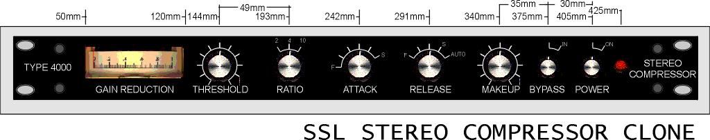
THE EXTERIOR:
SSL use Sifam (AL29, eg. Farnell:969-746) moving-coil meters and Sifam knobs (eg. RS:225-704) - types that you can get from RS, Farnell, or Canford if you want to look like the originals. Personally I find them pretty ugly, but your taste can be different, and some people might be more comfortable putting their valued mix thru' a homebrew machine, if it at least looks a little like something they know. Look at the Aliases and webpages at the end of this page if you need inspiration. You can actually use just about any meter that you like, if it is 5mA FSD or less, standard linear scale. But remember to change the (2K) resistor in series with the meter, if other than a 1mA meter is used.
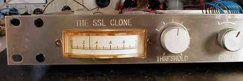
My Prototype's Front Panel Layout
Exterior design is a pretty important factor in how people will use - and thereby how they will judge - the unit. The pictures shows how I've chosen to do it. But then again, I'm really more into tubes, transformers and bakelite than solid state designs like this - though I must admit that I love The Clone's sonic qualities for a lot of mix types and for group compression on drums. Often, if you do your mixes entirely inside the computer, you'll be ending up with material that is hard to get to blend together - making individual track level setting very hard to do. This little box makes things much easier.
Pictures from various construction stages
PROBLEMS WHEN BUILDING:
If you read through the related error-fixing thread at Groupdiy.org, you'll see that the errors that the average DIY'er encounters when taking this problem on is limited to a few categories:
- Solder blobs, shorting PCB traces. The layout is very tight at places, so do yourself a favour and check and double-check - preferably with a magnifying glass.
- Bad soldering, not giving proper contact between component and PCB trace.
- Wrong component types or values. Specially error-of-magnitude on resistors.
- Wrong orientation of components. Including capacitors, IC's and diodes.
- Wrong wireing.
- Last, it's (for reasons unknown) common to forget mounting the wire-link at the control pcb, right beside the meter connection. This results in gross distortion in both channels.
DISCUSSION FORUMS AND RESOURCES:
A Detailed description of the SSL Clone project and posts about possible problems and solutions can be found at the GroupDIY forums. This is the first place you should check if you experience problems while building:
GroupDIY.org's SSL-clone META thread
Other links to builds:
NG-Recording's SSL-Clone page
Radiance builds a clone
www.uweb.ucsb.edu/~imacgreg/DIY_SSL.htm
www.fivefish.net/diy/SSL4000Compressor/default.htm
oxygene.dynip.com:8080/ssl/
shinybox.com/product_info.php?products_id=34
DATA:
Ratio: 2:1, 4:1, 10:1
Attack: 0.1, 0.3, 1, 3, 10, 30 mSec
Release: 0.1 sek, 0.3 sek, 0.6 sek, 1.2 sek, 2.4(Auto)
Make-up gain: 0 to 20dB adjustable
Threshold: -20 to +20dBm
Input: 50K Ohm electronically balanced
Output: 100 Ohm electronically balanced
Freq. Resp: Less than 15Hz to more than 35kHz within 3dB
Noise: Less than -80dB
Distortion: About -75dB unadjusted. Mostly 2nd harmonic.
ALIASES:
= SSL Logic FXG 384
= Alan Smart Research C2 Stereo Compressor
= Danfield 726
ERRATA:
If problems arises, errata and changes will be posted on this page.
Let me know how you're managing this project - and if you have information that could interest other diy-people I could link to it or put it on this page.
03-08-2002: Peter Cornell informed me of a article about the inter-changability between the 2150 and the new (and easier obtained) 2181 VCA.
18-09-2002. It seems that Stephen Giles has a version up and running with 2180 VCA's causing no problems... Today I also did a new PDF-file for the PCB artwork, as printing sometimes appear "thin" on the old one. Still rev#5. Thanks Kev!
21-09-2002: Recompiled the ssl.pdf file containing PCB artwork. Now rev# 6.
07-10-2002: Some minor changes in component overlay. A little larger pads. Meter sensitivity resistor marked.
15-01-2004: Steve "Swedish Chef" and Kev from recording.org has offer'd a ready-made set of PCB's at a good price:
10-05-2006: Component overlay revised to properly describe three mods necessary: Unity gain (two 15K resistors changed into 27K, look here), Ratio adjust (100K changed to 127K look here), and threshold de-sensitize (adding a resistor between pcb and threshold pot + look here) Now pcb rev#9
The GroupDIY forum would be a good place to ask questions about this project:
http://www.groupdiy.com/
...there's a good chance you will find me hanging around there...
REVISION HISTORY:
Pcb rev# 4 - Original. L input "+ shorts to gnd.
Pcb rev# 5 - 01-07-2002 - This - 1MB version - may print out thin.
Pcb rev# 5 - 20-08-2002
Pcb rev# 6 - 21-09-2002 - Cosmetic changes, new power transformer.
Pcb rev# 7 - 07-10-2002 - Some minor changes in component overlay
Pcb rev# 9 - 10-05-2006 - Component overlay changed as described above. No changes to actual pcb layout.
Schematic rev #5 - Minor changes
Schematic rev #7 - Changes 05-2006 - ratio, unity gain, and threshold - as described above.
Jakob Erland
www.gyraf.dk
10-05-2006
HOME
Shown:
10-2002