1176 DIY-page
Welcome to the Gyraf Audio DIY-1176-page.....
03. August 2004
Gyraf Do-It-Yourself 1176LN rev#F
This pages contain information about building your own version of the classic 1176 compressor.
I will try to update this page reguarly if anyone shows interest in its topics. Comments and corrections are welcome, but I can't promise to reply to all mail. If you do a project and describe it on your webpage, I'll be more than happy to add a link here, so others can benefit from your experiences.
Disclaimer: Notice that all information, schematics, layouts etc. are supplied "as is", and that we can in no way be held responsible for its acurateness, functionality or even safety.
Gyraf Audio shall not be responsible and disclaims all liability for any loss, liability, damage (whether direct or consequential) or expense of any nature whatsoever which may be suffered as a result of or which may be attributable, directly or indirectly, to the use of or reliance upon any information, links or service provided through this website.
The G1176:
A classic FET compressor. Not tubes, but a nice do-it-yourself project. Click the picture to see a series of pics of the first one being made.
This is an adaption of the original UREI 1176 LN rev#F to components and parts that is available (hopefully) everywhere. Adaption includes changing to standard european transistors, component values, Lundall output transformer and rotary switches for easier enclosure layout.
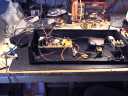
Click picture to watch the first unit being made...
The Schematic:
The Schematic for the 1176 compressor
We have updated the schematic to show approximate expected voltages around the transistors for easier error-tracing.
The PCB Layout:
The PCB Layout of the 10x16cm pcb board for the 1176 (300KB PDF-file). Rightclick the link and select "save as.."
NOTE: The PCB drawing is MIRROR'ED for easier printing, see the Pultec-DIY-page for details.
Gerber-format files for the PCB.
Thanks to Mikkel C. Simonsen for the conversion!
The parts list for the 1176
Here you can find a PDF- version of the complete 1176 manual, including adjustment procedure and all. Observe, that this is a VERY large file - 7.67MB. Rightclick the link and select "save as.." to save this on your own machine. Better get this while it's still there...
http://classes.berklee.edu/mpe/pdf_files/manuals_pdf/urei_1176ln.pdf
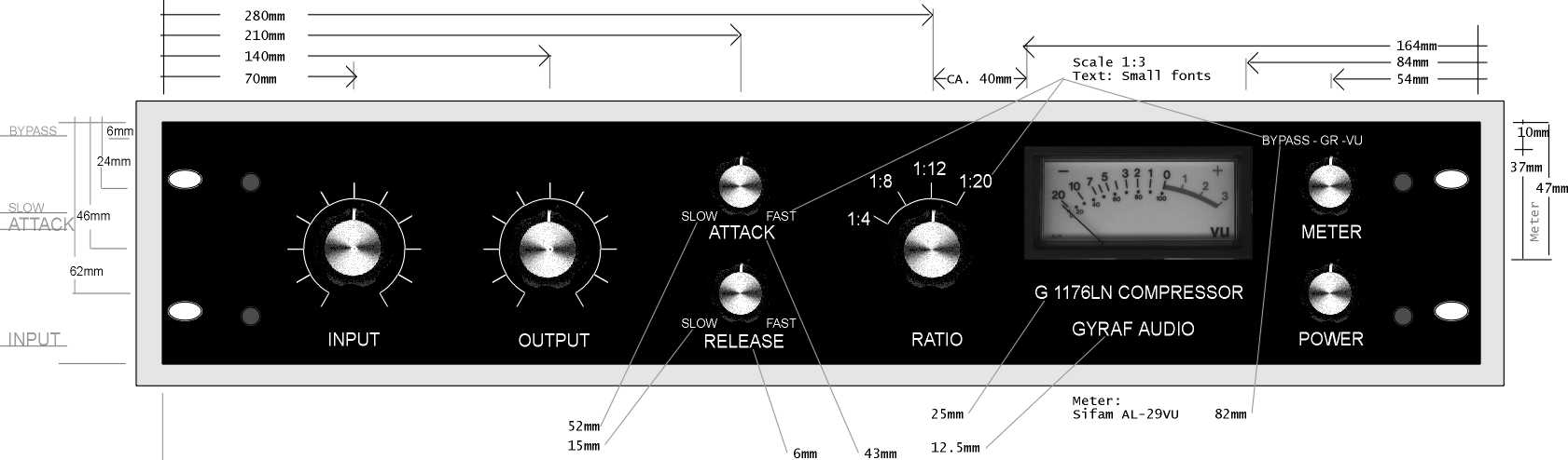
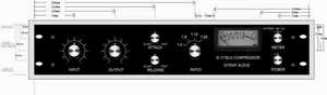
Front panel layout example...
On building the unit...
Building should be straight forward. Quite a lot of people has succeeded till now. But there are some common errors that you should avoid:
- Check component values before soldering in. Check specially resistors with an Ohm-meter.
- If using NTE substitutes for semiconductors, make absolutely sure that they are actually also pin-compatible. Some DIY'ers has had problems with this.
- Use a heat sink for the 7824 voltage regulator. A small one will often do.
- Check and double check the PCB for shorts and solder blobs before powering up.
- Remember that transistors aren't very forgiving. If they have been mounted wrong and powere'd up once, there's a good chance they are destroyed. Replace on suspicion.
- Make sure that the centre tap of the 2x24V at the power transformer is connected to ground
- Connect 0V/Ground to chassis at - and only at - the input XLR(F) connector. Here you can also connect the mains power ground from the IEC power connector if you need that.
- Note that the LL1540 input transformer is OPTIONAL. The "real" 1176 LN rev#F uses the electronically balanced input. The input transformer option is there simply because I like what it does for the sound. But it's not used in the original.
On adjusting the unit...
- Once the unit is built and checked, proceed with the adjustment procedure. You could use the procedure from the original .pdf manual, but that could be a bit tricky because we changed the bypass to be on the meter switch in stead of on the attack switch. So when they say "turn attack fully counterclockwise to bypass", it could translate into something like "bypass the unit with the meter switch". But that is not easy to follow, so here's a simplified adjustment procedure:
There is four adjustments.
1: "Q Bias". This is set by bypassing the unit, putting through a signal, adjusting in- and outlevel so output is around +1dB, and adjusting the trimmer untill a level drop of 1dB is acheived. This sets the FET start point in the beginning of it's conducting range.
2: "Dist. trim". Bypass the unit, input a ~1kHz, ~0dB signal, set unit gain to unity (by input- and output controls), and set trimmer for minimum distortion. If you have no dist.meter, simply set at middle position. Somehow this is not an important adjustment soundwise.
3: "GR meter Zero". No input signal. Meter switch in GR mode. Adjust untill meter reads 0dBVU.
4: "GR meter Trck" (tracking). Set ratio to 1:20, set Meter to bypass. Input a 1kHz, 50mV signal. Set input level to ~12'oclock. Set output level so you get 50mV at the output also (now you have unity gain). Now set the meter switch to "GR". Slowly turn up the level of your input signal (at the signal source, not with the input level control) while you monitor both input- and output levels with a voltmeter. When you reach a point where output level is half the input level, you have 6dB of gain reduction in the unit. Now set the "GR meter Trck" trimmer so the VU-meter reads -6dBVU. Remove input signal and (re)set "GR meter Zero" for a reading of 0dBVU. This calibrates the gr indication.
TroubleShooting:
- If you have problems, Please read the (rather long) Recording.org 1176 post before asking for help (also in that thread preferably, please):
Forum title: FEEDBACK FOR GYRAF 1176LN (repost) - LINK BROKEN
..no, sorry. That collection of information was shut down. Now we're reconstructing as much as this as we can on our new hangout:
http://www.groupdiy.com/
Orson Whitfield from GroupDIY has written a very good, compressed version of the thread about getting the G1176 running and fixing possible flaws. This is a great resource if you have problems during the process. Actually also worth a read before you are getting started:
Orson's G1176 DIY audio page for beginners
----------------
The SLAM mode...
By popular demand, here's information about how to include the hyped "Slam" or "Nuke" mode in this version of the 1176:
Slam/Nuke Mode Switch
If problems arises, errata and changes will be posted on this page.
ERRATA:..
28-04-2002: Peter Cornell mailed me with an error he'd found in the 1176 layout: The BF245 FET for metering gain reduction is connected mistakenly. This is corrected on PCB REV#6, 04-2002.
01-07-2002: Steffen Mueller mailed me, reminding me to mention that the VCA FETs - the BF 245's - must be the "A" type, the cutoff voltage being around -2V.
And the BC107C's does'nt really have to be "C" types - a lot of people have had problems getting hold on these. Go with the "B" type, it has plenty of Hfe for our purposes.
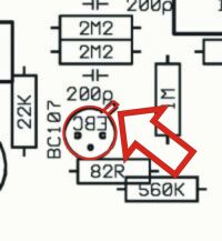
18-07-2002: Frank Rollen points out, that the BC107's on the main PCB, rev#6 are wierdly mounted, making assembleying hard.Actually these TO18-housings are by error wieved from the pcb-side. No harm should be done if you use the
rev#6 board, and just bend the middle transistor leg (the base) across to the hole. Remember to have the small metal edge on the transistor facing the "E".
Also updated the orientation of Q8, BD517, shown the wrong way around.
The "EBC" markings on the PCB were all correct though.
New version is PCB rev#7
21-09-2002: I've recompiled the PCB artwork PDF-files because of some printing problems on 600DPI printers.
23-10-2002: Updated schematic to show static DC voltages. This can be very usefull when tracking down errors..
06-11-2002: UPDATED THE COMPONENT LIST. NOW BETTER SIMILARITY WITH THE PCB.
21-01-2004: Gerber files added, thanks to Mikkel C. Simonsen!
If you let me know how you're managing this project - and if you have information that could interest other diy-people - I could link to it, or put it on this page.
In the meantime, check out the GroupDIY/Kev DIY-Page on Recording.org, with a lot of good links for this type of projects:
KEV'S DIY GROUP PAGE ON RECORDING.ORG
MNATS's 1176 PAGE - one of the best webpages covering this project - there even is an alternative PCB board layout:
MNATS's 1176 PAGE
And NRG-Recording, Germany, also takes a shot at this:
http://www.nrgrecording.de/diy.html
On the "LAB" forum at www.groupdiy.org there is a thread about correcting possible errors you may encount in the G1176:
http://www.groupdiy.com/
...there's a good chance you will find me hanging around there...
Also check out Juergen Haible's webpage about making your own 1176:
www.oldcrows.net/~jhaible/compressor
HOME
Shown:
01-2003
Jakob Erland
06-11-2002